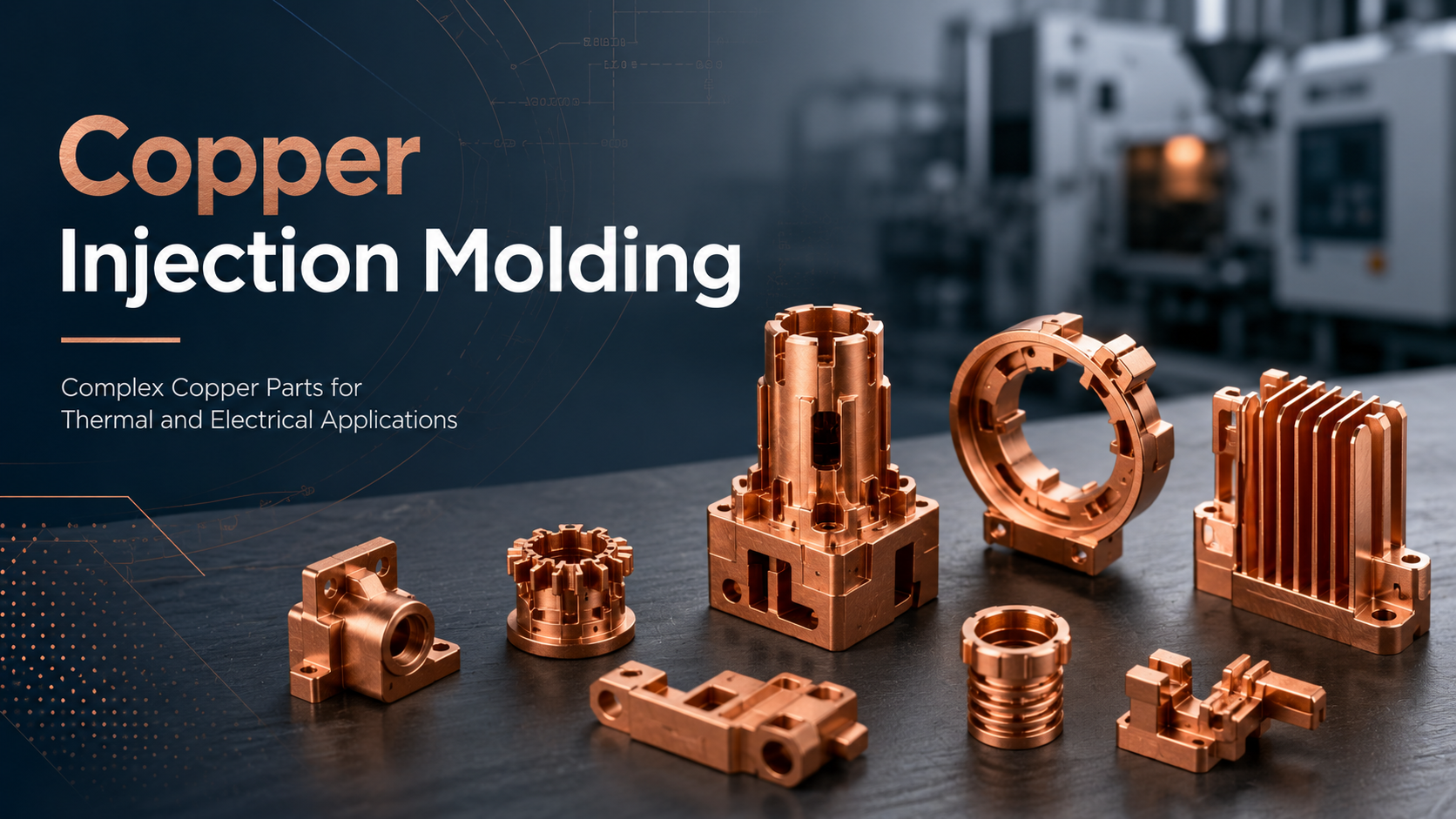
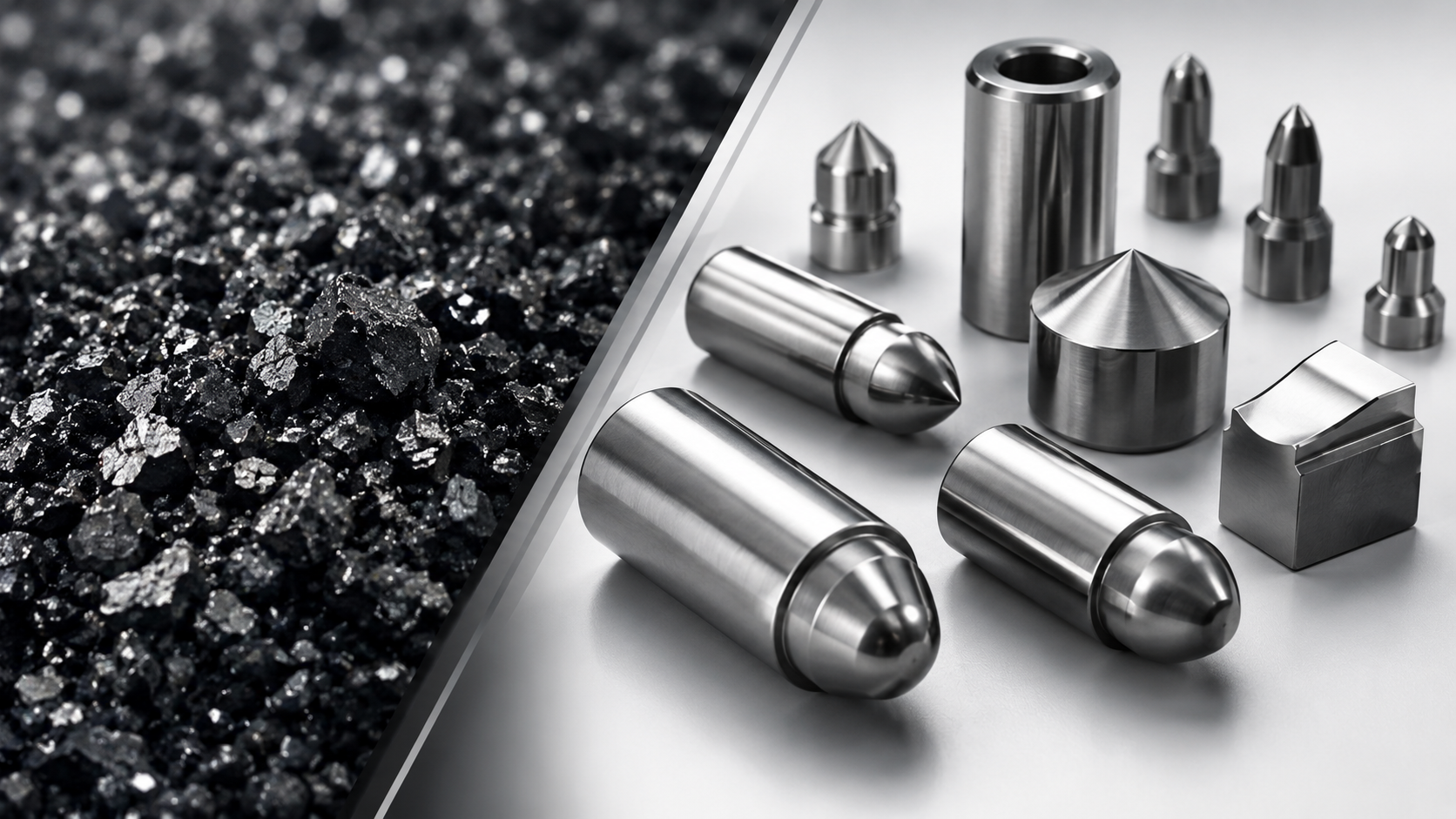
Copper injection molding, also known as Copper MIM or CuMIM, is a metal injection molding process used to produce small, complex copper parts with thermal and electrical performance requirements. It is especially suitable for components that require copper’s conductivity but are difficult or expensive to produce by CNC machining, stamping, or conventional forming methods.
Read this article for copper metal injection molding for custom copper parts, and the hands-on experience you can trust. Send your copper part drawings now, and our skilled team will provide you with free, special evaluation on a custom machining plan and cost-saving advice.

What Is Copper Injection Molding?
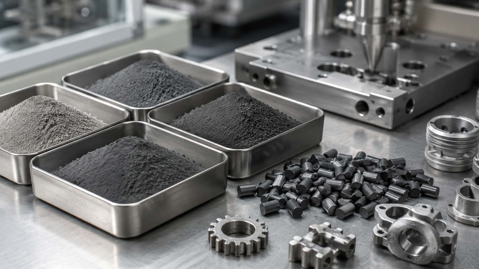
Copper injection molding is a metal injection molding process that combines fine copper or copper alloy powder with a temporary binder system. This mixture, called feedstock, is injected into a mold cavity to form the required part shape. After molding, the binder is removed through debinding, and the part is sintered at high temperature to create a dense metal copper component.
The final part is not plastic. It is a metal part made from copper or copper-based material.
The basic process usually includes:
-
Feedstock preparation: Copper powder is mixed with a binder system to create moldable feedstock.
-
Injection molding: The feedstock is injected into a precision mold to form the green part.
-
Debinding: The binder is removed through a controlled thermal or solvent-based process.
-
Sintering: The part is heated to bond the metal particles and form a dense copper component.
-
Secondary operations: Depending on the drawing requirements, the part may need CNC machining, tapping, polishing, plating, cleaning, or inspection.
Copper injection molding is especially useful when the part has complex geometry, small features, thin walls, internal details, or a shape that would be difficult to produce efficiently by traditional machining.
Why Use Copper for Metal Injection Molded Parts?
Copper is used in engineering applications because of its excellent thermal conductivity and electrical conductivity. These properties make copper suitable for parts that need to transfer heat, carry current, provide grounding, or support electronic functions.
In many industries, the main challenge is not only selecting copper as the material. The harder challenge is manufacturing a copper component with the required shape, size, and functional features.
Copper injection molding helps solve this problem by allowing engineers to design small and complex copper parts that combine multiple functions into one component.
Common reasons to use copper in MIM parts include:
-
High thermal conductivity for heat dissipation
-
High electrical conductivity for current-carrying components
-
Design freedom for small and complex geometries
-
Ability to integrate mounting, contact, and thermal features
-
Repeatable production for medium-to-high volume projects
-
Potential cost reduction compared with CNC machining in complex parts
However, the final thermal and electrical performance depends on powder quality, sintering density, oxygen control, porosity, material selection, part geometry, and testing requirements. Therefore, conductivity values should be confirmed according to the specific project instead of assumed from general copper material data.

When Should You Choose Copper Injection Molding?
Copper injection molding is usually considered when the part is small, complex, and required in medium-to-high production volume.
It is often suitable when:
-
The part requires copper’s thermal or electrical performance
-
The geometry is too complex for simple stamping
-
CNC machining becomes expensive at production volume
-
The part includes small holes, thin walls, fins, pins, or integrated features
-
Several functions need to be combined into one copper part
-
The customer needs repeatable production after design validation
Copper MIM is not always the first choice for prototypes or simple shapes. If the part is large, simple, or only needed in very small quantity, CNC machining or stamping may be more practical.
A good way to think about copper injection molding is this:
Choose copper injection molding when part complexity and production volume justify the mold tooling and sintering process.
Typical Applications of Copper Injection Molding
Copper injection molding is mainly used for small and complex copper components where thermal conductivity, electrical conductivity, or compact functional design is important.
Copper Heat Sinks and Thermal Management Parts
Copper is widely used for thermal management because it can transfer heat efficiently. Copper injection molding can be considered for compact heat sinks, heat spreaders, thermal transfer parts, and cooling-related components with complex geometry.
For example, a copper heat sink may include:
-
Pin-fin structures
-
Thin-wall features
-
Integrated mounting holes
-
Complex three-dimensional shapes
-
Contact surfaces for electronic modules
-
Small thermal paths inside limited assembly space
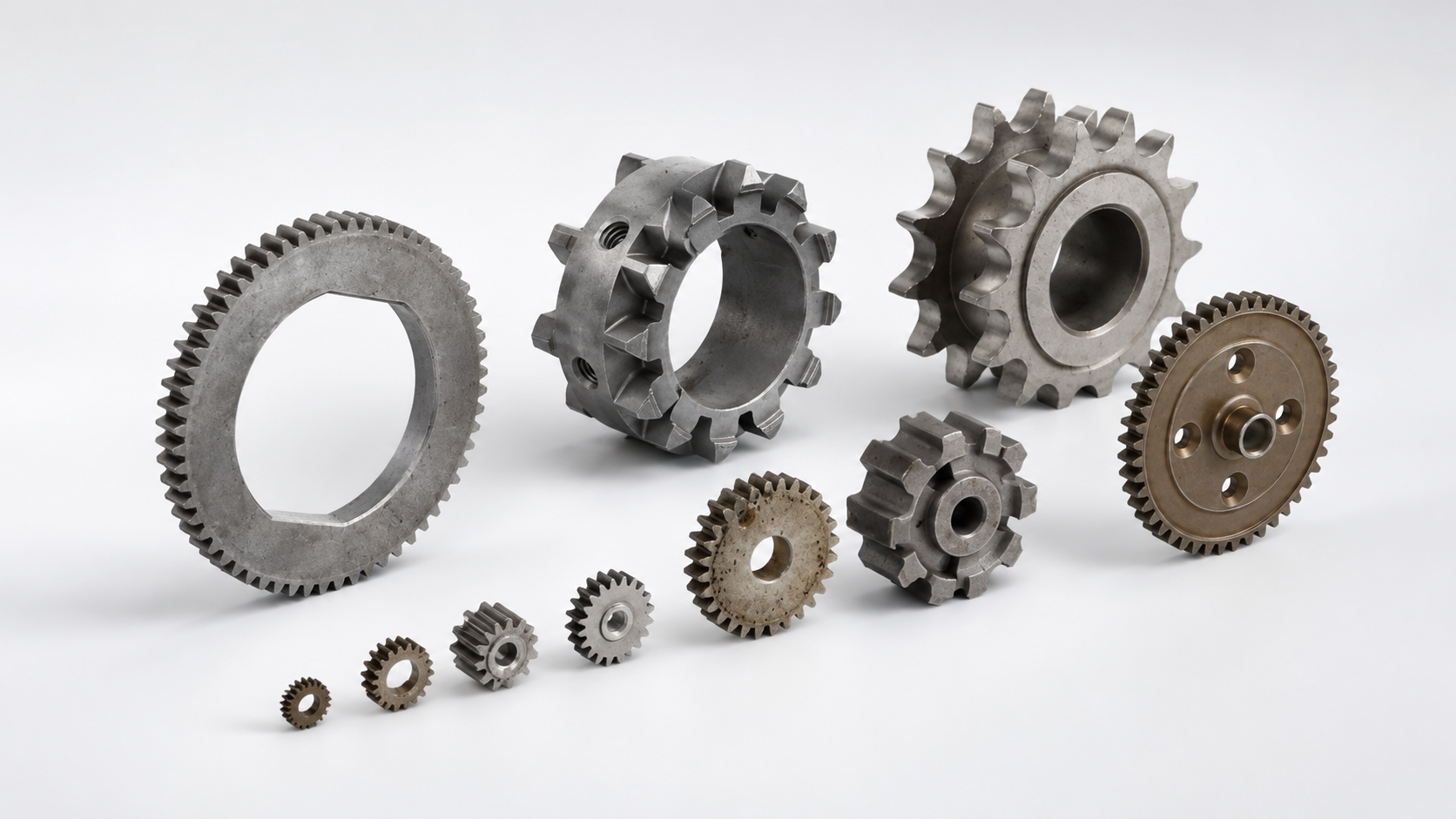
CNC machining can produce many copper heat sinks, but machining becomes less efficient when the design includes many small fins, pins, cavities, or repeated complex features. Copper MIM may provide better design freedom and more stable production efficiency for these types of parts.
Electrical Contacts and Conductive Components
Copper and copper alloys are commonly used for electrical contacts, conductive parts, terminals, and current-carrying components.
For simple flat terminals, stamping is usually the most cost-effective process. But when the part has a three-dimensional structure, complex contact geometry, small functional details, or integrated mechanical features, copper injection molding may be a better option.
Copper MIM can be considered for:
-
Electrical contacts
-
Conductive inserts
-
Connector parts
-
Switching components
-
Grounding components
-
Custom conductive elements
The correct material depends on conductivity, strength, hardness, wear resistance, surface finish, and plating requirements.
Connectors and Terminals
Connectors and terminals often require stable dimensions, reliable contact surfaces, and good electrical performance. When the design is simple and sheet-like, stamping is normally preferred. When the design becomes compact, three-dimensional, or difficult to form from sheet metal, Copper MIM can be considered.
Copper injection molding allows more freedom for part geometry, especially when the connector part includes mounting features, local thickness changes, internal shapes, or non-flat contact structures.
Power Electronics Components
Power electronics often require parts that can manage heat and conduct electricity at the same time. Copper injection molding may be used for custom copper parts in power modules, control systems, electrical assemblies, and thermal management structures.
These parts may need to combine:
-
Heat transfer
-
Current carrying
-
Mechanical support
-
Mounting features
-
Compact assembly design
For this reason, copper MIM is often evaluated when the part is not just a simple conductor, but a functional component inside a compact system.
Automotive, Optical, and Sensor Components
Automotive electronics, optical systems, sensors, and industrial control modules often use small metal parts with demanding dimensional and functional requirements. Copper injection molding may be suitable when these parts require both copper performance and complex geometry.
Possible applications include:
-
Sensor components
-
Thermal transfer parts
-
Small conductive parts
-
Optical module components
-
Automotive electronic parts
-
Compact copper brackets or functional inserts
In these applications, early design review is important because material choice, geometry, tolerance, surface finish, and inspection requirements can strongly affect manufacturing feasibility.
Copper Materials Used in Metal Injection Molding
Copper injection molding can involve pure copper or copper-based materials. The best material depends on the required thermal conductivity, electrical conductivity, strength, hardness, wear resistance, corrosion resistance, and production conditions.
Pure Copper
Pure copper is often selected when thermal conductivity or electrical conductivity is the main requirement. It can be used for heat sinks, conductive components, contacts, and thermal management parts.
However, pure copper is softer than many engineering metals. If the part also requires wear resistance, higher strength, or better mechanical durability, a copper alloy may need to be considered.
Brass
Brass is a copper-zinc alloy. It may be considered when the part needs a balance of machinability, corrosion resistance, mechanical strength, and moderate conductivity.
Brass MIM may be used for small mechanical parts, fittings, decorative functional parts, or components where pure copper conductivity is not the only priority.
Bronze
Bronze is usually based on copper and tin, sometimes with additional alloying elements. Compared with pure copper, bronze can provide better strength, wear resistance, and corrosion resistance in certain applications.
Bronze MIM may be considered for small wear-related parts, mechanical components, bushings, contact parts, or complex copper alloy parts.
Copper-Tungsten
Copper-tungsten is a copper-based composite material that combines the conductivity of copper with the high-temperature resistance, wear resistance, and low thermal expansion characteristics of tungsten.
It may be considered for electrical contacts, heat-resistant parts, thermal management components, and applications where pure copper does not provide enough wear or high-temperature performance.
Copper-tungsten MIM should be reviewed carefully because the final properties depend on powder composition, sintering process, density, geometry, and project requirements.
Material Selection Should Be Project-Based
Not every copper-based material is suitable for every MIM project. Material availability depends on powder feedstock, part geometry, required properties, production volume, and testing requirements.
For custom copper injection molded parts, material selection should be confirmed during the engineering review stage instead of decided only by general material names.
When to Choose Copper Injection Molding Over Other Processes
| Manufacturing Process | Main Advantages | Main Limitations | Best Suited For |
| Copper Injection Molding | Complex geometry, integrated features, lower unit cost after tooling | Mold tooling required; not ideal for very low volume or large simple parts | Small, complex 3D copper parts with medium-to-high volume |
| CNC Machining | No mold required, flexible for prototypes, strong local precision | Higher unit cost for complex or high-volume parts | Prototypes, low-volume parts, or tight local tolerances |
| Stamping | Fast and cost-effective for flat copper parts | Limited for complex 3D shapes or variable thickness | Flat terminals, sheet metal contacts, and thin conductive parts |
| Die Casting | Suitable for some larger metal parts and high-volume casting | Pure copper is difficult to die cast; less suitable for small precision parts | Larger or less precise parts, depending on material and geometry |
In general, CNC machining is best for prototypes and low-volume precision parts, stamping is best for flat copper sheet parts, and Copper Injection Molding is best for small, complex, three-dimensional copper parts at medium-to-high volume. For small precision pure copper parts, Copper MIM or CNC machining is usually more practical than conventional die casting.
Work with XY-GLOBAL for Custom Copper Injection Molded Parts
If you are evaluating copper injection molding for a custom part, XY-GLOBAL can help review your drawing, compare possible manufacturing routes, and check whether Copper MIM is suitable for your geometry, material requirement, tolerance, and production volume.
XY-GLOBAL supports custom precision manufacturing projects involving MIM parts, CNC machined parts, and secondary finishing operations. For copper injection molded parts, we can assist with early design review, process selection, quotation evaluation, post-machining, surface treatment, and production planning.
To start a project, you can send us your 3D file, 2D drawing, material requirement, quantity, and application details. Our team will review the part structure and provide feedback on manufacturability, process options, and quotation feasibility.
Share:
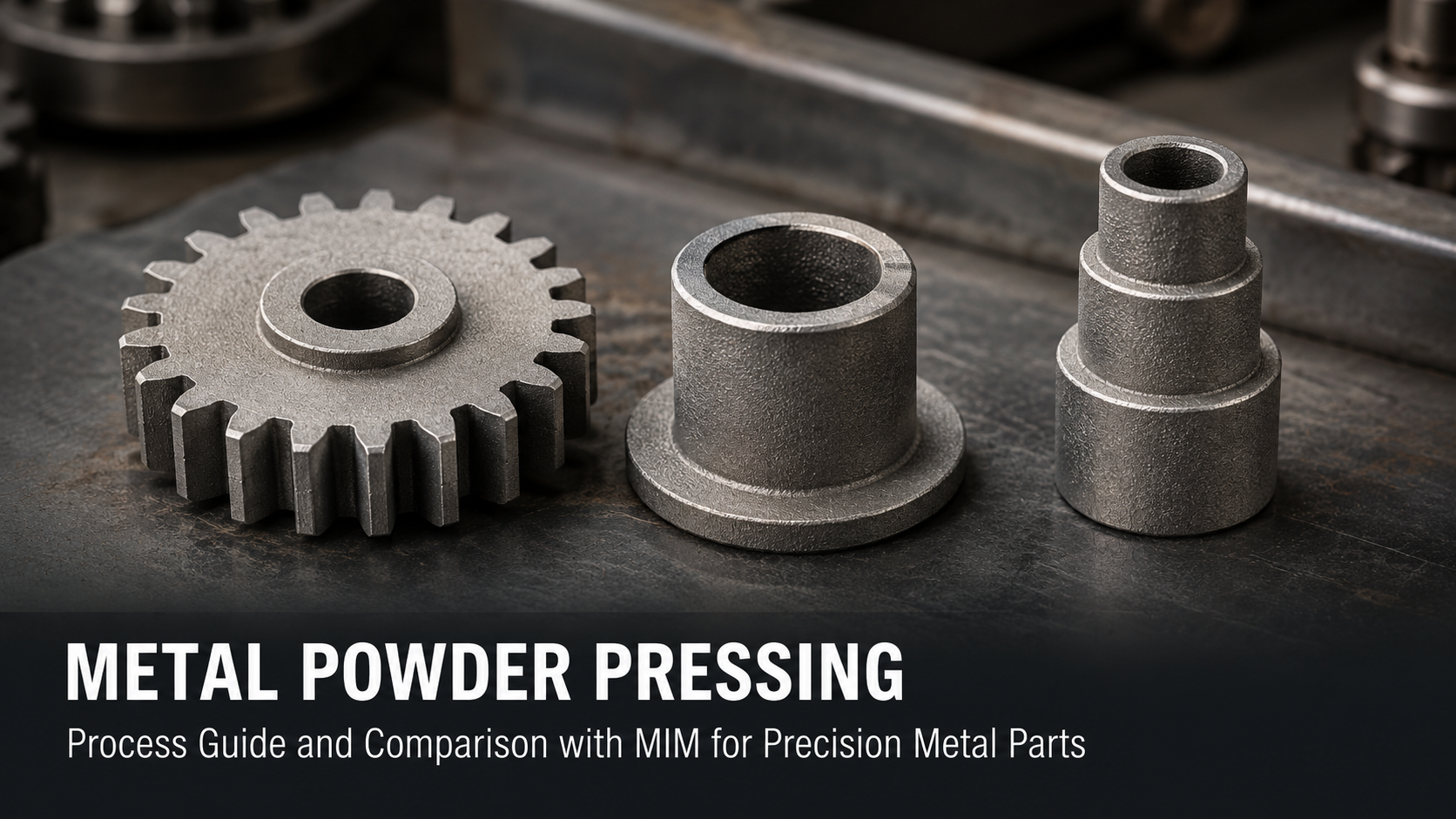
Metal Powder Pressing: Process Guide and Comparison with MIM for Precision Metal Parts