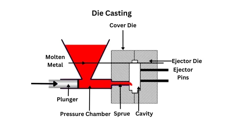
The mold for MIM has a large influence on the product dimensional capability during production. Once the component is ejected from the tool there remains little capability to adjust dimensions except with extra cost. MIM tooling looks similar to that used in plastic injection molding, although molds are oversized to account for the large sintering shrinkage. In most instances, the tool set consists of one to four cavities serviced by tool pieces that move in coordination with the opening, molding, and closing actions; such as slides and ejector pins.
Part, Tool, and process design are very important. In MIM there are additional concerns with the higher thermal conductivity and density of the feedstock. Metal particles make the binder much more thermally conductive when compared to plastics. Likewise, the metal particles increase the feedstock density significantly over typical plastics. Otherwise, MIM relies on similar principles for plastic molding.

Blemishes from Tooling
A successful MIM part design allows for locating the parting line, ejector pin marks, witness lines, and gate in non-critical areas. Often the gate is located on a parting line, so these two blemishes go hand-in-hand. Parting lines can be placed along component edges to reduce visibility. Sometimes features within the mold set are inserted to allow changes, replacement, interchangeability, and servicing. These inserted components will leave witness lines where they blend into the parent part surface.
Early in the design process, the designer needs to consider placement of these blemishes in areas where they will not detract from the function or aesthetics. Alternatively, the gate can be removed by grinding or polishing after molding, but prior to de-binding and sintering, since the material is easily removed then.



Share:
Abrasive Vs Pure Waterjet Cutting, Which Is Better
Metal Injection Molding, Materials and Properties