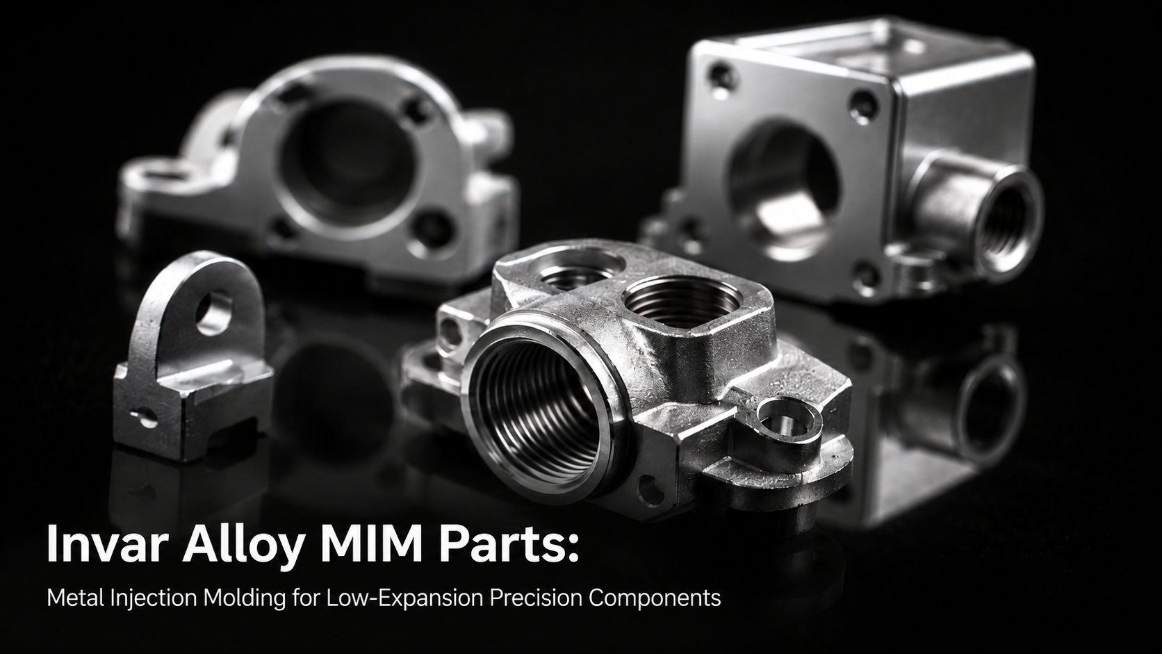
When a laser system drifts out of alignment on a hot afternoon, or a satellite bracket shifts by a few microns as it passes from sunlight into shadow, the culprit is usually thermal expansion. For engineers designing optical, semiconductor, and aerospace hardware, keeping dimensions stable across a temperature range is often more important than saving weight or cost. This is exactly the problem Invar alloy was invented to solve — and metal injection molding (MIM) now makes it possible to produce small, geometrically complex Invar parts economically and in volume, without the machining headaches this alloy is notorious for.

What Is Invar Alloy (FeNi36)?
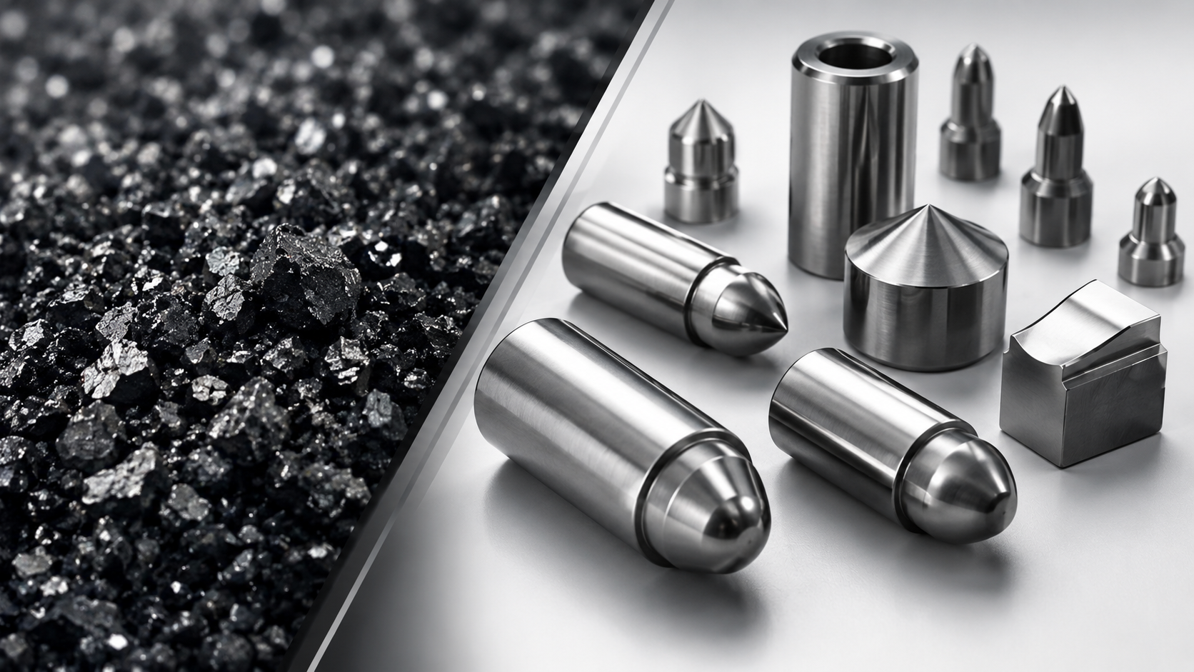
Invar is a nickel-iron alloy containing approximately 36% nickel, with the balance iron and small additions of carbon, manganese, and silicon. It was discovered in 1896 by Swiss physicist Charles Édouard Guillaume, who later won the Nobel Prize in Physics largely for this work. The name "Invar" comes from "invariable," referring to its defining trait: a coefficient of thermal expansion (CTE) close to zero across a normal operating temperature range.
In industry, Invar is also known as Invar 36, FeNi36, Alloy 36, or by the designation UNS K93601. Beyond its low expansion, Invar offers reasonable mechanical strength and is ferromagnetic, though it has only moderate corrosion resistance and typically requires plating or coating in humid or marine environments.
Why Low Thermal Expansion Matters in Precision Manufacturing
Most engineering metals expand and contract noticeably with temperature. Standard steels have a CTE around 11–13 ppm/°C, aluminum alloys around 22–24 ppm/°C, and titanium around 8.6 ppm/°C. Invar, by contrast, has a CTE of roughly 1.2 ppm/°C near room temperature — an order of magnitude lower than steel.
In everyday hardware, this difference is invisible. But in optical assemblies, semiconductor lithography stages, laser diode packages, fiber alignment fixtures, and satellite structures, a few microns of dimensional drift can mean a lens goes out of focus, an interferometer loses accuracy, or a wafer stage loses registration. In these applications, engineers deliberately choose Invar so that the structure holding a precision component stays dimensionally stable even as ambient or operating temperature fluctuates.
Can Invar Be Processed by Metal Injection Molding?
Yes — but it demands tighter process control than many common MIM alloys. Invar's defining property comes from a very specific 64:36 iron-to-nickel ratio, and even a 1% shift in nickel content can measurably change the resulting CTE. This means feedstock preparation, debinding, and sintering all need to preserve compositional accuracy from powder to finished part.
Two process risks matter most. First, oxidation: the iron portion of the alloy is prone to oxidizing during thermal debinding and early sintering, which can alter surface chemistry and mechanical performance if not run in a controlled reducing atmosphere (typically hydrogen) or vacuum. Second, densification: Invar MIM parts need to reach a high fraction of theoretical density — generally above 95–98% — for the microstructure to deliver a stable, repeatable CTE. Fine, spherical, gas-atomized FeNi36 powder, usually in the 4–20 micron range, is used as the MIM feedstock base to support this level of control.

The MIM Production Process for Invar Parts
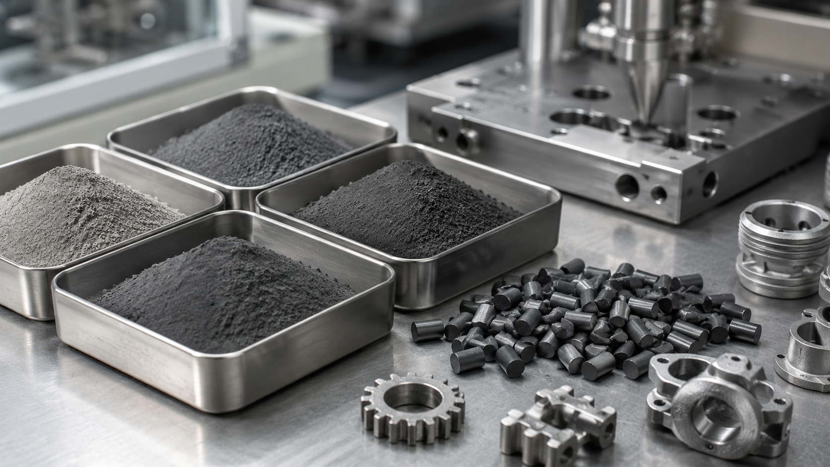
The overall workflow for Invar MIM follows the same core stages as other metal injection molding programs, with a few alloy-specific adjustments:
Feedstock compounding: Fine Invar 36 powder is blended with a multi-component binder system to form a homogeneous, moldable feedstock.
Injection molding: The feedstock is injection molded into a "green" part at the target geometry, oversized to compensate for shrinkage during sintering.
Debinding: Binder is removed through solvent and/or thermal debinding, leaving a fragile "brown" part made only of metal powder held together by light sintering necks.
Sintering: The brown part is sintered at high temperature in a hydrogen or vacuum furnace, following a carefully controlled profile to reach full density while preserving the Ni:Fe ratio. Parts typically shrink 15–20% linearly during this stage, which must be built into the original tooling design.
Secondary operations: Depending on the application, parts may go through sizing, a stabilizing heat treatment to lock in the target CTE, precision machining of critical reference surfaces, or plating for corrosion protection.
Typical Applications of Invar MIM Components
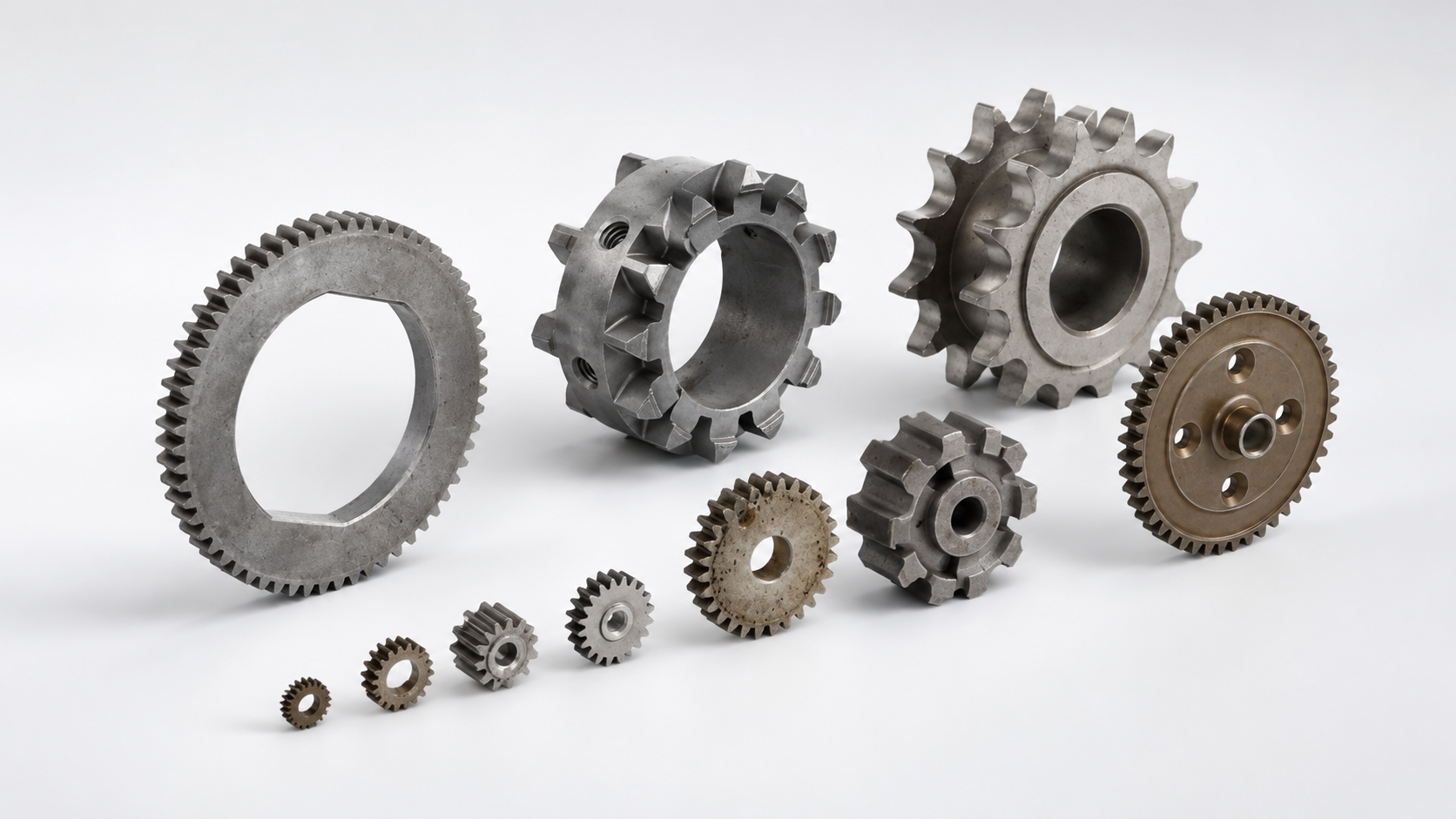
Invar MIM parts are typically small, geometrically complex, and produced in moderate to high volumes — exactly the profile MIM is best suited for. Common applications include:
Optical instrument housings and lens barrel components for telescopes, cameras, and laser systems, where lens spacing must not drift with temperature. Fiber optic connector ferrules and alignment fixtures that keep fiber cores precisely positioned. Semiconductor lithography stage brackets and wafer handling fixtures, where nanometer-level positioning accuracy depends on a stable frame. Satellite and aerospace structural brackets and antenna mounts exposed to extreme temperature swings between sunlight and shadow. Precision measurement instrument frames, such as interferometers and gauge bodies. Cryogenic sensor housings and seals that must hold tolerance from room temperature down to extremely low operating temperatures.

Invar MIM vs. CNC Machining vs. Investment Casting
Engineers evaluating production routes for Invar parts generally compare three options.
CNC machining is often the default for prototypes or very low volumes. However, Invar is notoriously difficult to machine — it is "gummy," work-hardens quickly, and wears tooling fast, which drives up cost significantly for small, complex geometries.
Investment casting can produce larger Invar parts, but dimensional precision is lower, and porosity can introduce inconsistency in the CTE and mechanical properties — a serious concern for precision applications.
Metal injection molding produces near-net-shape parts with repeatable dimensional accuracy, and can form threads, thin walls, and undercuts in a single step that would require multiple machining operations otherwise. For small Invar components (generally under 100 grams) needed in the thousands of units, MIM is typically the most cost-effective route, especially once tooling cost is amortized across production volume.
Design Guidelines for Invar MIM Parts
A few practical guidelines help engineers get the most out of Invar MIM:
Keep wall thickness in the 0.5–6 mm range where possible, to support uniform shrinkage and sintering behavior. Avoid sharp internal corners, which concentrate stress and increase the risk of cracking during debinding. For applications requiring extremely tight CTE control (tolerances tighter than roughly ±0.1%), plan for a secondary machining step on critical reference surfaces after sintering. Consider a post-sinter stabilizing heat treatment — typically annealing near 830°C followed by a controlled cooling profile — to lock in a consistent thermal expansion behavior. Because Invar has only moderate corrosion resistance, factor in nickel or gold plating for parts exposed to humidity or long-term storage.

Why Work with XY-Global for Invar MIM Parts
Invar is not a forgiving material to get wrong — composition drift, oxidation, or incomplete densification can quietly erase the exact property engineers are paying for. XY-Global brings over 15 years of MIM and CIM manufacturing experience, more than 46 R&D-developed materials, and precision tolerance capability down to 1µm, backed by a free DFM feasibility report and free prototype samples so the CTE and dimensional performance of a design can be validated before committing to production tooling. With a track record serving optical, semiconductor, and aerospace clients, our engineering team can help evaluate whether Invar MIM is the right fit for a given design, and where secondary operations may be needed to hit demanding specifications.
FAQ
What does CTE mean, and why is Invar's CTE so low?
CTE (coefficient of thermal expansion) measures how much a material's dimensions change per degree of temperature change. Invar's near-zero CTE comes from a magnetic effect called the Invar effect, in which thermal expansion is largely offset by a change in the alloy's magnetic state as temperature rises.
Is Invar magnetic?
Yes, Invar is ferromagnetic at room temperature, which is actually part of the mechanism behind its low thermal expansion behavior.
Can Invar MIM parts be used in cryogenic applications?
Yes. Invar's dimensional stability extends to low-temperature environments, making it a common choice for cryogenic sensor housings and related hardware, though the specific application should be validated against the operating temperature range.
How does the cost of Invar MIM compare to machined Invar parts?
For small, complex parts in moderate-to-high volumes, MIM is typically more cost-effective than machining once tooling is amortized, since Invar's poor machinability drives up CNC machining costs significantly.
What tolerances can be achieved with Invar MIM parts?
Standard MIM tolerances of roughly ±0.3–0.5% of a given dimension are achievable as-sintered; tighter tolerances can be reached with secondary machining or sizing on critical features.
Does Invar need surface treatment?
Often yes. Because Invar has only moderate corrosion resistance, plating (such as nickel or gold) is commonly applied for parts exposed to humidity or long-term outdoor or marine use.
Conclusion
Invar's near-zero thermal expansion makes it indispensable wherever dimensional stability under temperature change is non-negotiable — from optical instruments to semiconductor stages to aerospace structures. Metal injection molding offers a practical way to produce small, complex Invar components economically and repeatably, avoiding the machining difficulties this alloy is known for, provided the process carefully controls composition, oxidation, and densification. Engineers considering Invar MIM for a new design are welcome to request a free DFM feasibility review to evaluate manufacturability before committing to tooling.
Compartir:
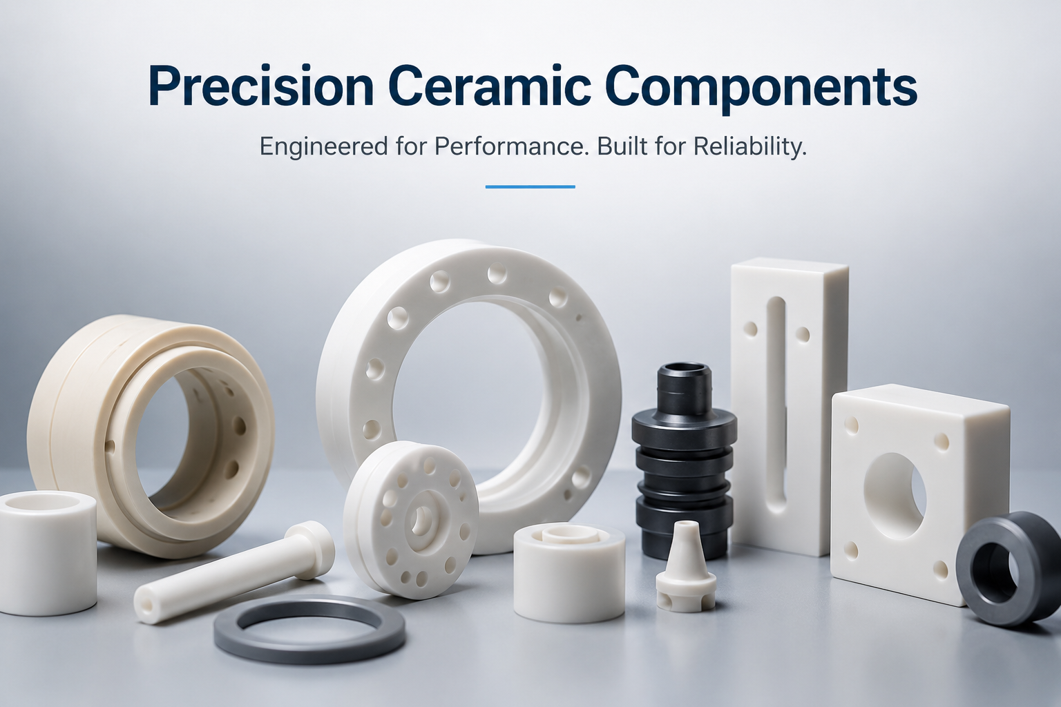
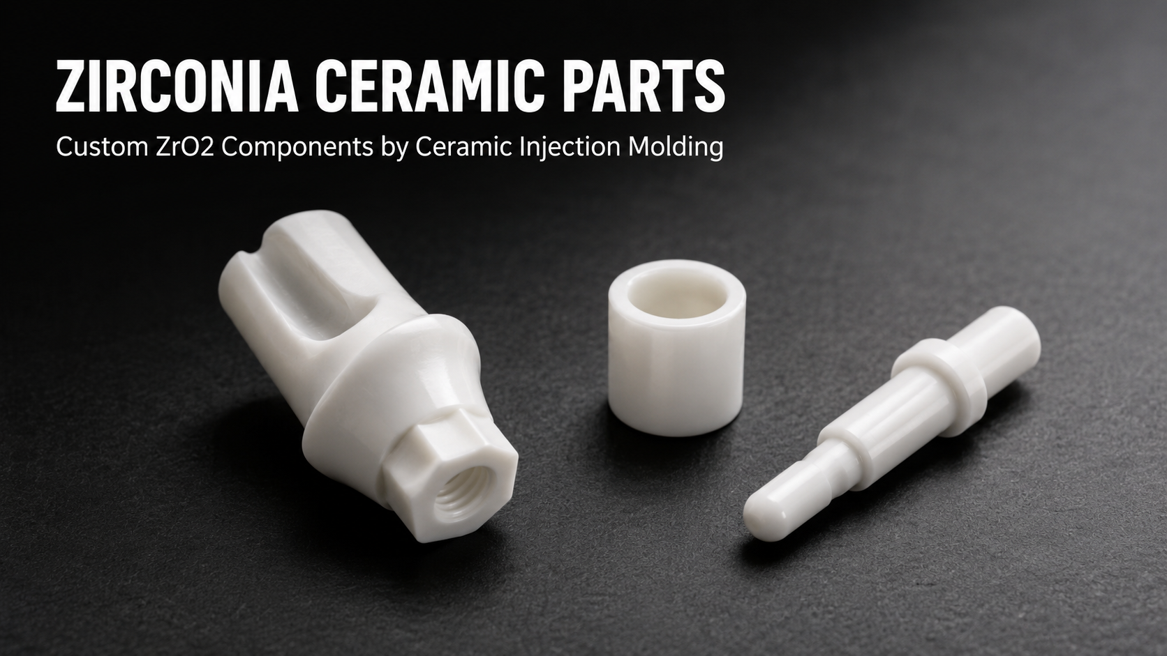
Precision Ceramic Components for High-Performance Industrial Applications